Using Force Layout
A Force directed layout is a rendering of a physics simulation in which each node pushes away from other nodes while edges pull the nodes together. There is no intrinsic meaning to node position or edge length in a force-directed layout. Rather, the rendering is designed to result in a graph that is visually pleasing and reasonably easy to navigate.
For more detailed information, see Force-directed Graph Drawing.
GraphXR uses a specific force-directed layout by default, but you can:
Adjust force layout parameters for the entire graph, and restore default settings.
Randomize node positions for all or part of the graph.
Temporarily disable force layout for all or part the graph.
Run a brief force layout simulation for the entire graph.
Adjusting Force layout parameters
The Force tab of the Layout panel provides a set of sliders to adjust default layout parameters for the entire graph.
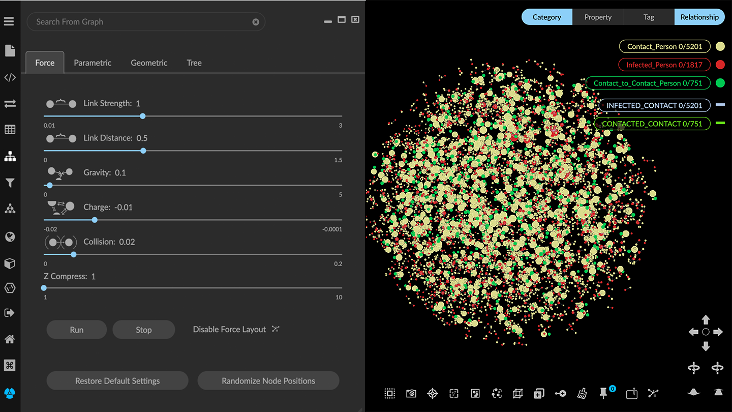
You can adjust parameters as follows:
Link Strength. Adjusts how strongly the links (i.e. edges) pull the nodes together.
Link Distance. Adjusts the distance between nodes (i.e. edge length).
Gravity. Pulls the nodes toward the center of the graph space, that is, the point the view rotates around when nothing is selected.
Charge. Adjusts how strongly the nodes push away from one another.
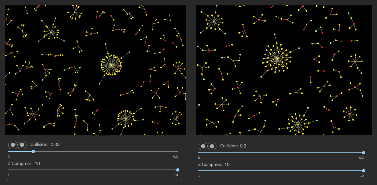
Collision. Adjusts the degree to which nodes are allowed to overlap each other. This is especially useful in a 2D layout, to un-stack nodes projected on top of one another. When set all the way to the right, some overlap can still occur.
Z Compress. Compresses nodes on the Z axis to become a flatter, more 2D layout. To project a 3D view to near-2D, set the Z-Compress slider all the way to the rightmost position. You will still be able to rotate the data in 3D.
NOTE: The Z Compress slider is hidden if the 2D Mode checkbox is checked in the Project>Settings panel.
Click the Restore Default Settings button to restore the sliders to their default positions and re-render the default force layout for the selected graph.
Any pinned node is excluded from adjustment, and left where it was placed. This applies to nodes you’ve arranged manually in the project space, and to those pinned automatically using a geometric layout. To release pinned nodes, you must either use the Pin/Release toolbar icon, or the Release button in the Geometric layout panel.
Restricting layouts to 2D
When exploring high-dimensional data, 3D visualization provides a powerful advantage. However, you can work exclusively in 2D mode if desired. For example, a flat 2D project space might be desired to create and share views for reports of various kinds.
To set the project space to 2D:
In the Project panel and Settings tab, click the 2D Mode checkbox.
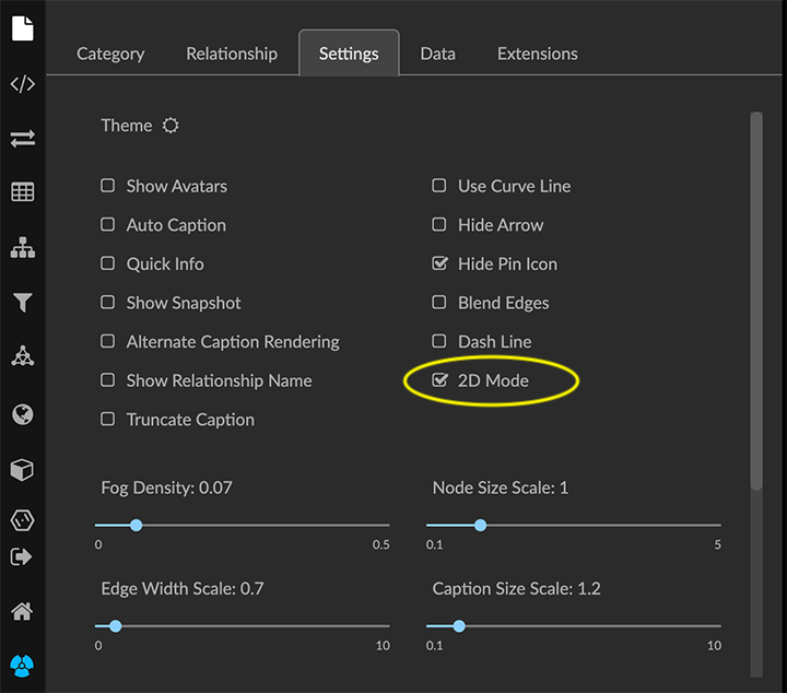
In the Force layout tab, the Z-Compress slider is no longer displayed. Project data are now arranged on a flat plane, and the data cannot be rotated in 3D.
Many Geometric layouts translate well to a purely 2D layout: Line, Circle, Spiral, and Grid, and hierarchical Rings or Trees.
Randomizing node positions
In Force layout, nodes are rendered in randomized positions. The Randomize Node Positions button lets you render a different random arrangement either for selected data, or all data if no data are selected (except for pinned nodes).
To randomize a force-directed layout:
Select nodes using any method.
Note: If none are selected, all node positions are randomized, except for any pinned nodes.Make sure that the label next to the icon reads Disable Force Layout. This means that force layout is currently enabled, and your selection will be randomized according to the current force layout parameters.
Click the Randomize Node Positions button to render a different random force layout for your selection.
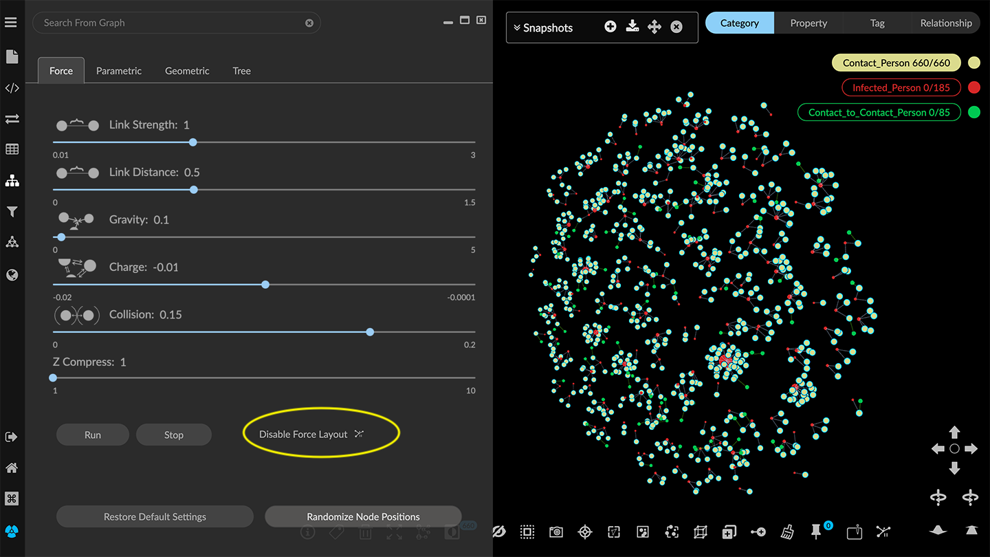
Disabling Force Layout
You can disable the force layout for all or part of the graph. This causes selected nodes to be rendered in a random, more compact arrangement that does not use a force-directed simulation. This can help you focus quickly on subgraphs of interest.
To disable force layout and randomize node positions:
Select nodes using any method.
Click the force layout icon. The text next to the icon should now read Enable Force Layout, which means that force layout is currently disabled.
Click the Randomize Node Positions button to display a different random order for your selection.
The selected data are randomized in a more compact layout, while the data not selected remains in its original force layout.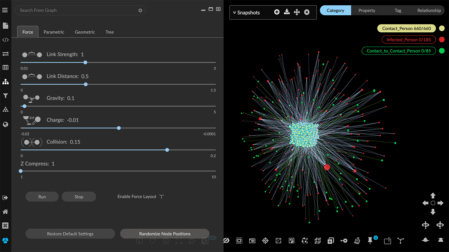
NOTE: If no data are selected, all node positions are randomized in a non-force layout, except for any pinned nodes.
Click the icon next to Enable Force Layout at any time to return the selected nodes to force-directed layout.
Using Run and Stop
With force layout enabled, you can click Run to run a brief (1- or 2- second) force layout simulation for the entire graph. Click Stop to freeze the layout when you see a rendering you like.